


Brushless DC motors
From PCs to drones, the Brushless DC (BLDC) motor has become a preferred choice and it is for a good reason, BLDC motors are more efficient and exhibit higher power density than their brushed counterparts. BLDC motors have less wear and tear and allow for the deployment of lighter and less expensive motors in applications. This means they live longer, are more reliable and require less maintenance. They are also less noisy than brushed motors. However, designing BLDC motors poses numerous challenges the major one being the delivery of optimum efficiency for a given performance point.
Power loss in MOSFETS
Typical BLDC motors have a three-phase stator that rotates the rotor through an electronic control scheme which incorporates a 3 phase inverter circuit. The inverter circuit continually switches currents in the stator windings in synchronization with the rotor position as ascertained by the Hall sensors. The magnetic flux generated in the stator then interacts with the rotor to create torque and build up speed for the motor. To understand power loss in MOSFETS we are going to review a BLDC motor application that built using the following discrete components;
- Power management
- Digital control
- Drivers
- Three-phase inverter
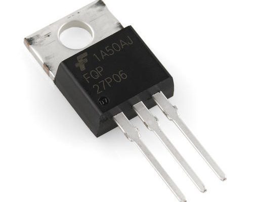
The three-phase inverter comprises three half bridges. Each half is made up of High-Side (HS) MOSFETs and Low-Side (LS) MOSFETs. Every half-bridge has an output voltage of between 0 V and which is regulated by the application of a pulse width modulated signal to the HS and LS MOSFETs. The PWM is generated by the onboard microcontroller and is delivered to the MOSFETS through the gate drive Ics.

Q1, Q2, Q3 are high-side MOSFETs while Q4, Q5, and Q6 are low-side MOSFETs. Understanding losses incurred during operation of the power inverter stage are very fundamental in ensuring the cost-efficient design of BLDC motors
You May Also Like This : How to Power and Control Brushless DC Motors
Power loss calculation in 3 phase inverter
Power dissipation in a 3-phase motor inverter consist diode, conduction, and switching losses. To establish the best price and performance MOSFET, it is important to understand the split of these losses.
Conduction losses
When the MOSFET is switched ON, it behaves like a resistor and the conduction losses can be established using the formula below;
![]()
To obtain the average value of the MOSFET conduction losses you have to integrate the instantaneous power losses over the switching cycle using the formula below:
![]()
is the RMS value of the MOSFET on-state current. MOSFET’s is temperature dependent hence we need to factor this in in the calculation of conduction power loss.

is the junction temperature.
Switching loss
To calculate the switching loss of a MOSFET, you need to;
- Establish the duration of switching transition for switch ON and switch OFF
- Obtain the product of , and the duration of switching transition so as to establish single switching transition energy
- Establish the number of switching transitions over a single electrical period of the motor
- Obtain the product of the single switch transition energy and the number of switching transitions in order to obtain the total switching loss.
- Follow these stops for turn ON and turn OFF so as to establish losses on both occasions.
It is also prudent to ascertain the gate drive current for both turn ON and turn OFF.

![]()
![]()
is the total gate resistance.

Diode loss
A MOSFET’s diode has two different modes of operation, conduction, and demagnetization. In synchronous rectification the diode conducts during dead time, that is before and after turn ON and turn OFF.
Optimized MOSFET selection
Subjecting MOSFETs to this procedure enables designers to make informed decisions regarding the best price/performance MOSFET.
Related posts:
 LED Connectors: Streamlining Assembly Efficiency
 Zero-Ohm Resistors: Uses and Benefits
 ITT Cannon Trident Cost-Effective Connectors
 Smallest UWB Module Delivers Low-Power For IoT
 Roller Machine for Home Use
 How to Secure your Blockchain Solutions
 3D PRINTING: IS IT THE INDUSTRIAL REVOLUTION OF THE 21ST CENTURY?
 XMC1202 LED Lighting Shield for Arduino
 How to Choose LED Drivers and LED Power Supplies
 LED Lighting for Commercial Applications
 Sensirion SEK-SHTxx/SGP30 Sensor Evaluation Kit
 Examining the Use of IoT for Smart Manufacturing


