


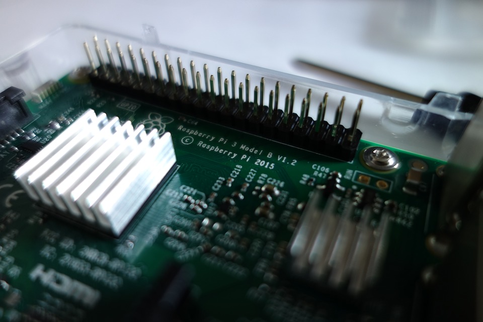
The BLDC Motor Driver Evaluation Board of the MCP8024 TQFP is used to demonstrate the MCP8024 drive capabilities. A total stand-alone engine operator for brushless DC motors (BLDC) is the MCP8024 TQFP BLDC Motor Driver Evaluation Board. The board is capable of riding up to 15A and 28V with a three-phase brushless DC motor. The board’s input voltage variety is between 7V and 28V. The MCP8024 on board uses internal rectifier diodes to produce 5V and 12V.
Motor gate driver MCP8024 3-Phase Brushless DC (BLDC)
The board uses the motor gate driver MCP8024 3-Phase Brushless DC (BLDC) and the plug-in module (PIM) dsPIC33FJ32MC204 to implement a 6-step BLDC motor controller. In a BLDC motor system, it is being used to test the it of Computer chip. As presented, the MCP8024 TQFP BLDC Motor Driver Evaluation Board is prepared to use one on-board toggle switch to stop and start the engine, plus one on-board potentiometer to set the engine speed. The test board will power a BLDC engine with up to 28V supply voltage and up to 15A motor current. It offers a 6-step trapezoidal control dataset with a 750 mW buck converter, 5V and 12V LDO, high-to-low voltage translators, present sense operational amplifiers and Auditorium-effect inputs. The assessment board gives an impression of the designation of the power supplies and the six Pulse-Width Modulation (PWM) inputs on board.
The mcp8024 TQFP BLDC motor driver evaluation board kit includes:
• MCP8024 TQFP BLDC Motor Driver Evaluation Board (ADM00557)
• dsPIC33FJ32MC204 Plug-In-Module (MA330017)
• Information Sheet
FEATURES
The MCP8024 TQFP BLDC Motor Driver Evaluation Board has the following features:
- Input Operating Voltage Range: +7.0V to +28V
- Maximum of 500 mA of gate drive current for external N-Channel MOSFETs
- Drives up to a 15A BLDC motor
- PICkit 3, MPLAB REAL ICE in-circuit emulator and MPLAB ICD 3 debugger interfaces
- Speed control potentiometer
- Terminal block for 5V and 12V Hall-effect sensors
- SPI and I2C headers for user communications
- Programmable external MOSFET overcurrent protection
- Programmable PWM dead-time protection
- 750 mW Buck Regulator with resistor-programmable output voltage
- ON/OFF momentary contact switch
- Reset momentary contact switch
- Spare user-programmable momentary contact switch
- PWM signal LED indicators
- 100-pin dsPIC DSC PIM header for use with MA330017 compatible PIMs
- Programmable PWM blanking time for current switching spikes
- Complete “C” source code
Configuring the The MCP8024
The MCP8024 has setup registers which can be used to change the device’s operating variables. The parameters were changed using the DE2 messaging bus to transmit data to the MCP8024. The transmission bus DE2 is a half-duplex, 9600 baud, 8-bit data, 1-stop bit, 1-start bit, no parity, serial communication link. To communicate with the registers, the user can attach code to the firmware of the evaluation board. The code of the evaluation board includes a subroutine that initializes the registers of MCP8024.
Related posts:
 Zero-Ohm Resistors: Uses and Benefits
 UNDERSTANDING CONNECTORS AND THEIR SPECIFICATIONS
 RMS-to-DC Converters: Voltage & Power
 An Introduction to the processes of Soldering and Welding
 Design Considerations for Cellular IoT in 5G Network
 ITT Cannon Trident Cost-Effective Connectors
 How to Secure your Blockchain Solutions
 Roller Machine for Home Use
 Connectors for Energy Storage Systems and Applications
 What are the Different Types of Molex Mega-Fit Power Connectors
 XMC1202 LED Lighting Shield for Arduino
 3D PRINTING: IS IT THE INDUSTRIAL REVOLUTION OF THE 21ST CENTURY?


