


Microchip Technology
Microchip Technology is arguably the world’s leading provider of microcontroller connectivity, analog, power management and FPGA semiconductors. It manufactures easy to use development tools. Microchip have a comprehensive product portfolio that enables customers to design tools and machines at a low cost and with minimal risks. One notable product from their portfolio is the Motor Control Starter Kit. Their starter kit goes a long way to demonstrate the capabilities of the low cost 16 bit Motor control and mTouch devices.
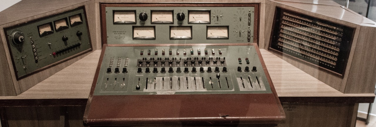
Motor Control Starter Kit.
Michropchip’s Motor Control starter kit comes equipped with the following contents;
- Motor Control Starter Kit Board
- BLDC motor
- 9V power supply
- USB cable
Motor Starter Kit Board
The boards top assembly exhibits key features which include;
- Microchip dsPIC33FJ16MC102
- 9Vpower connector
- Motor Connector
- 3-phase inverter
- BLDC motor
- BEMF feedback
- Power LED
- Push Button
- Current feedback
- Capacitive slider
- Programmer power LED
- User LEDs
Its bottom assembly embodies the following;
- Power supply regulators
- On board debugger
- Programmer USB connector
Motor control Application
The kit’s software and hardware is a unique version of the AN1160. The main difference lies in how the overcurrent fault functionality is implemented. The dsPIC33FJ16MC102 has a built-in analog comparator that enables instant detection of an overcurrent condition thus enabling the immediate hardware shutdown of the PWM outputs. To even further the board’s flexibility, the over current levels can easily be set in software.
Motor current passing through a shunt is amplified using an Op Amp and is available as input on an analog pin of the dsPIC33FJ16MC102. This input can be configured in the software as both a comparator input and as an ADC input. Reading the current using the ADC module makes it possible to implement more complex control algorithms for instance the single shunt.
The comparator’s output is wired externally to the PWM to close fault detection loop. In the event the current exceeds the level set in the software, then the comparator toggles its output and the PWM is going to be shut down immediately.
MTouch capacitive slider application
The capacitive slider is implemented based on AN1250. A two-channel slider is administered on the motor Control Starter Kit. Each of these two channels is connected to the to an analog input located on the dcPIC33FJ16MC102. Each of the channels is charged by the CTMU module using a fixed current over a given period. The capacitance of each of the channel varies depending on the position of the user’s finger over the slider. The value is highest when the slider is not being touched. When the charging time elapses, the CTMU stops charging hence triggering the ADC to start sampling and converting the voltage on each of the capacitors to a numerical value.
Motor Control and mTouch integration
The dsPIC33FJMC102 operates at a maximum frequency of 16MHz and has enough resources to run the Motor Control Starter Kit demonstration application which includes the motor control and the mTouch features.
Motor control applications constantly generate noise spikes on the supply levels making it hard for capacitive touch applications to operate. To overcome this, capacitive slider measurements are taken when no MOSFETS are switching. This is achieved by reducing the capacitance charging time to a minimum by increasing the charging current and synchronizing it with the PWM cycle.
The dsPIC33FJ16MC102’s ADC module allows for simultaneous sampling of 4 different analog channels. Three channels are needed for the BEMF feed-back from the motor’s phases leaving one channel for the CTMU module. Both channels are sampled and converted alternatively on successive PWM cycles.
The CTMU module has a trigger that it uses to start and stop charging of the slider’s capacitors. This trigger is configured in a manner that the ADC starts conversion a couple of nanoseconds after the capacitors cease charging. This way no PWM switching happens while sampling the voltage on the capacitor.
The schematic diagram


