


Voltage Combination
Low voltage is often preferred in many applications but there are applications that require high voltages of up to hundreds of volts. This includes applications like haptic devices, print head drivers, scientific instruments, specialized sensors and piezoelectric motors. This makes the combination of low and high voltages inevitable. Incorporation of both low and high voltages in the same design poses numerous challenges though. It involves the development of higher voltage DC rail and incorporation of voltage amplifiers while ensuring that relevant safety and regulatory mandates are met.
Developing a high voltage Rail
To create a high voltage DC rail, engineers can either develop high voltage supply or purchase one. Designing a high current voltage supply that supplies low currents is not difficult. There are two ways to go about it:
- Boost-mode DC/DC switching- This is ideal for circumstances where only low voltage DC sources are available
- Doubling circuits- This is applicable where an AC line is available
A doubler converts peak AC value into DC that is twice the value. The amount of current provided by a double is dependent on the size of capacitor hence the higher the current required the bigger the sizes of capacitors required.
Whether you use boost-mode or the voltage doubling approach, you need to be very careful with regards to the layout, arcing and user safety. It is for this reason that engineers prefer commercially available high voltage supply like the EMCO series AGP01P-5. It is PCB mounted, has a profile of 3.25 mm and has a volume of 1639 cubic mm. It operates from a DC source of between 0.7 to 5 volts while delivering 100 volts at 10Ma. There are high voltage supply units capable of higher voltages and currents. Some are operated from a DC rail while others are AC powered. You just need to pick one that well fits with your application.
You May Also Like This : “Low Voltage Circuit Breakers“
-
Analog drive
With the power rail set, providing high voltage analog amplification is the next thing. There are two ways of accomplishing this.
-
A standard Voltage op amp
You can use a standard low voltage op-amp with booster transistors incorporated on the output side. This converts the low voltage output swing to a broader and higher voltage range. One such op-amp is the LT105. It is a high-speed op-amp and its output can be boosted with to a bipolar 125-volt rail through three pairs of PNP/NPN transistors.
This approach requires a number of additional active and passive discrete components. Moreover, the NPN/PNP transistor types picked have to be matched with similar or complementary specifications for parameters like gain and slew among others so as to ensure that symmetry in bipolar operation.
-
Dedicated op amp
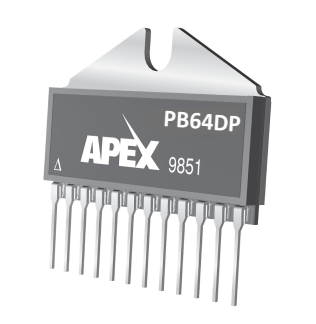
You can also use an op-amp that is inherently designed for high voltage operation. These op amps are not monolithic but are packaged in a small module. They are used alongside low voltage op-amp that acts as a signal buffer. One such op-amp is the PB64.
Safety standards
High voltage, unlike low voltage, is surrounded by industry and standards for user and system safety. The standards differ from region to region and based on the end application. Designs under 60 volts have very few restrictions though. There are many standard-setting organizations including UL, IPC, and IRC to mention a few. The higher the voltages the stricter the requirements on the physical arrangement of the design as well as the electrical failure and mechanical structure. Most of these standards focused on the voltage as opposed to current levels. Voltage is the primary source of risk to both user and circuitry. By closely aligning voltage and mechanical design considerations, these standards ensure that;
- The internal arrangement does not allow for arcing or flashover
- The mechanical or packing failure that could expose the user to unsafe potentials does not occur.
- The high internal voltages are not accessible to users
The standards define the creepage and clearance at different various voltage levels. Creepage is the distance between exposed points as measured along the surface of a PCB. Clearance is the shortest distance between two conductive parts when measured through air. These distances increase with the increase in voltage level. Creepage and clearance are also affected by the operating environment, the material used amongst other factors. Therefore, it’s very important for you to go through these standards so that you get a deeper insight into the relevant guidelines.
Conclusion
Combining both low and high voltages on the same circuit can be done successfully and safely. There are a couple of ways to achieve have designers get the liberty to choose that which best fits their application. There are well-established standards to ensure that ensure the safety of both the user and circuit. It takes a careful balance of the two to successfully combine low and high voltages in the same circuit.
Related posts:
 Mesh Networking: Bluetooth 5 Mesh Networking to Advance IoT
 Audio Amplifier: Introduction to TAS2505-Q1EVM Audio Amplifier
 ABB Rotary Switches At Enrgtech | ABB Manufacturer
 Uses Of Raspberry Pi – Power Supply, Robot with Raspberry Pi
 Key Capabilities of Bluetooth LE to Make the Future of Audio
 Motor Control Starter Kit-Microchip Technology
 LED Lighting: How to Choose The Best LED Lighting?
 How the IoT is Changing the Transportation System
 Current Sensors: Effective High Power Isolated Current Sensors
 PROTECTION MODES FOR LED DRIVERS
 Choosing The Right RTOS For IoT Platform
 Industrial IoT Solutions and Applications


