


In an excerpt of a book, two professors, San Kyeong and Michael Pecht, mention the fundamentals and major principles that help electrical engineers in the interconnection of devices through electrical connectors 101.
According to the book “Electrical Connectors: Design, Manufacturer, test and selection,” professors wrote that there is always a hierarchy in any electronic system. Add to this, interconnections of different components on the board structure a network. This network help components to communicate and set a strong network of devices and gadgets. Such connectors are beneficial in several ways, whether it is signal transmission or distribution of power among the devices. Connectors help us in ensuring the proper functioning of the devices and connectivity among them.
What Are Connectors In Electronics- A Non-Technical Definition?
These could be wires, cables, and modules that are electronically connected. Such cables and wires include the conductor material that allows the passage of current. These electromechanical components build a bridge between electronics devices. A connector connects the following things:
- Connects different parts of the same circuit
- Connects different electrical circuits
- Builds large circuit network
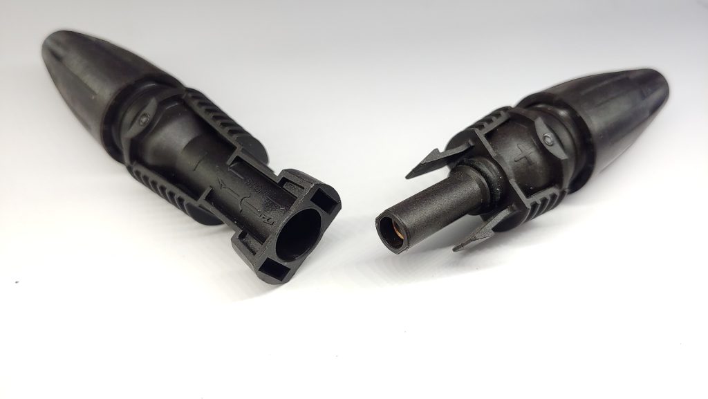
Connectors are gender biased:
This is a fact, and there are genders in electronics components; usually, there are two types of connectors on a gender basis.
- Male connectors
- Female connectors
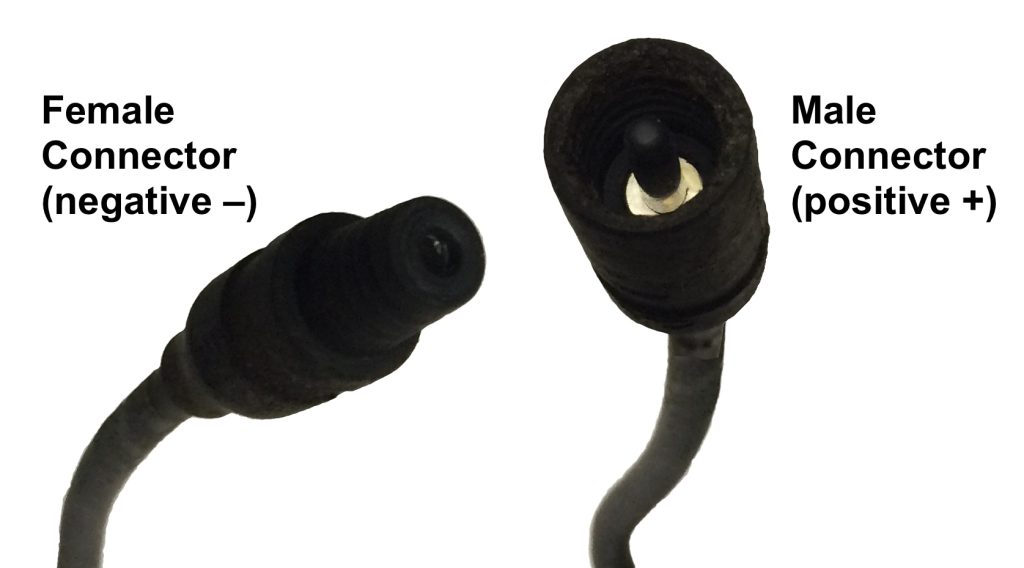
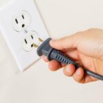
What is a male connector?
This is the plug that connects with the female connector.
What is a female connector?
This is the socket and connects with the plug or male connector.
Removable and Fixed Connectors:
Sometimes, engineers need connectors that can be removed easily. These are also known as portable, like magnetic chargers’ pins. On the other hand, there are fixed connectors that restrain the fluctuation and current blockage. These are permanent electrical joints, and engineers use them as a long-term solution.
In addition to this, sometimes two different shapes of terminal ends. In this situation, experts recommend the adapter that helps in connecting two different sorts of terminal ends.
Sorting of connectors – considering termination endpoints:
When we are talking about the termination ends, we have 3 sorts of common connectors. These are stated below:
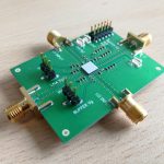
- Board-to-board connectors
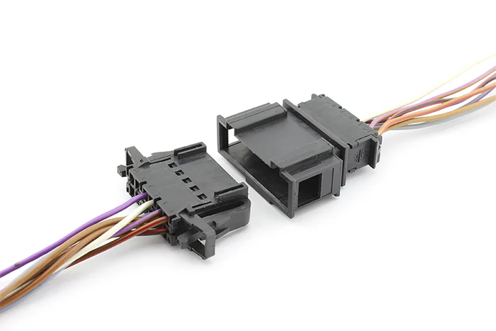
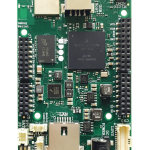
- Wire-to-board connectors are also known as cable-to-board connectors.
- Wire-to-wire connectors are also known as cable-to-cable connectors.
As per the termination endpoint, engineers have distributed them in a way to utilize them to the maximum extent and make it easier to connect a couple of electronics devices.
Almost all the circuits have interconnections, from the computer motherboard to the vacuum cleaner circuits.
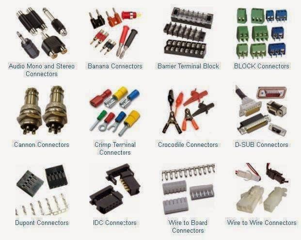
Types of connectors – unique functionalities:
On the basis of functions, electrical connectors have the below-mentioned four types.
PCB mount connectors
when you solder a wire and make an end-to-end connect. This soldering end helps wires and cables connect.
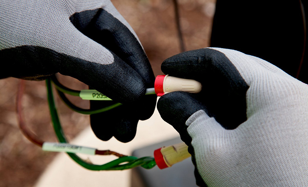
Butt connectors
These are also known as splice connectors. This connector permanently connects the two end terminals.
Panel connectors
These are also known as chassis connectors; they permanently connect to the equipment from one end. Another terminal end connects with other devices.
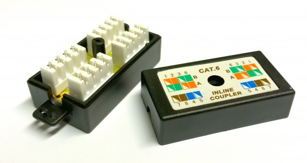
Inline connector
This connector is also a permanent connector. Engineers permanently connect with a cable, and this cable connects with other terminals.
Levels of connectors on the basis of inter-connectivity:
These are interconnectivity methods and ways. And referred to as below-mentioned in the electronics industry.
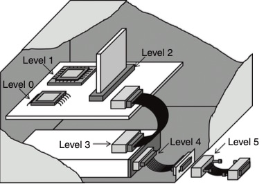
- Level 0 – when we connect the basic circuit and its lead.
- Level 1 – component lead and PCB connection like sockets, DIP, and switches.
- Level 2 – when we connect two PCBs, for instance, motherboard connection with daughter board.
- Level 3 – Connection between 2 sub-assemblies.
- Level 4 – connection of subassembly with input, output device.
- Level 5 – Link between a printer and computer. This level interconnects the two totally separate devices that work independently.
What is the physical construction of an electronic connector?
Engineers use different sorts of connectors that are variants of each other. But electronic connectors are different in the following characteristics:
- Material from which connectors are made
- The size of the connectors are different
- Insulation is also different for different electronics connectors
- Resistance of different connectors is different
- Pinout and terminal ends are different in shapes
- Durability difference
Add to the above-mentioned points, the visuals of the connectors also help the users.
Easy-to-assemble connectors for frequent connections are common in the electronics and electrical industry. Moreover, a good connector is easy to connect and identifiable visually easily. Some of the massive production of electronic connectors also include custom size and shape connectors.
Selection of material and demand for electrical connectors 101:
Manufacturing suppliers and engineers design the connectors for two sorts of materials:
- Conductor material
When deciding on the right material, the manufacturing of a connector is mandatory. The extent of the material depends upon lots of factors; few of them are mentioned here.
- Resilience
- Mechanical strength of the material
- Resistant
- Conduction of the material
- Electrical resistance for the insulating material is paramount
- Temperature resistance for the insulation material
- Fitting of the terminal end
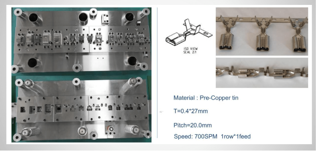
During the manufacturing of the connectors, engineers use copper material for better conductivity of the connector. For cost reduction, the manufacturer is also using brass, beryllium copper, and phosphor bronze.
What happens when a connector fails?
As an electronics connector is a bridge, the flow of current, data, and voltage, so the failure of a connector would stop this electrical communication. Devices may not remain connected; the overall functioning and flow of the circuit network get disturbed.
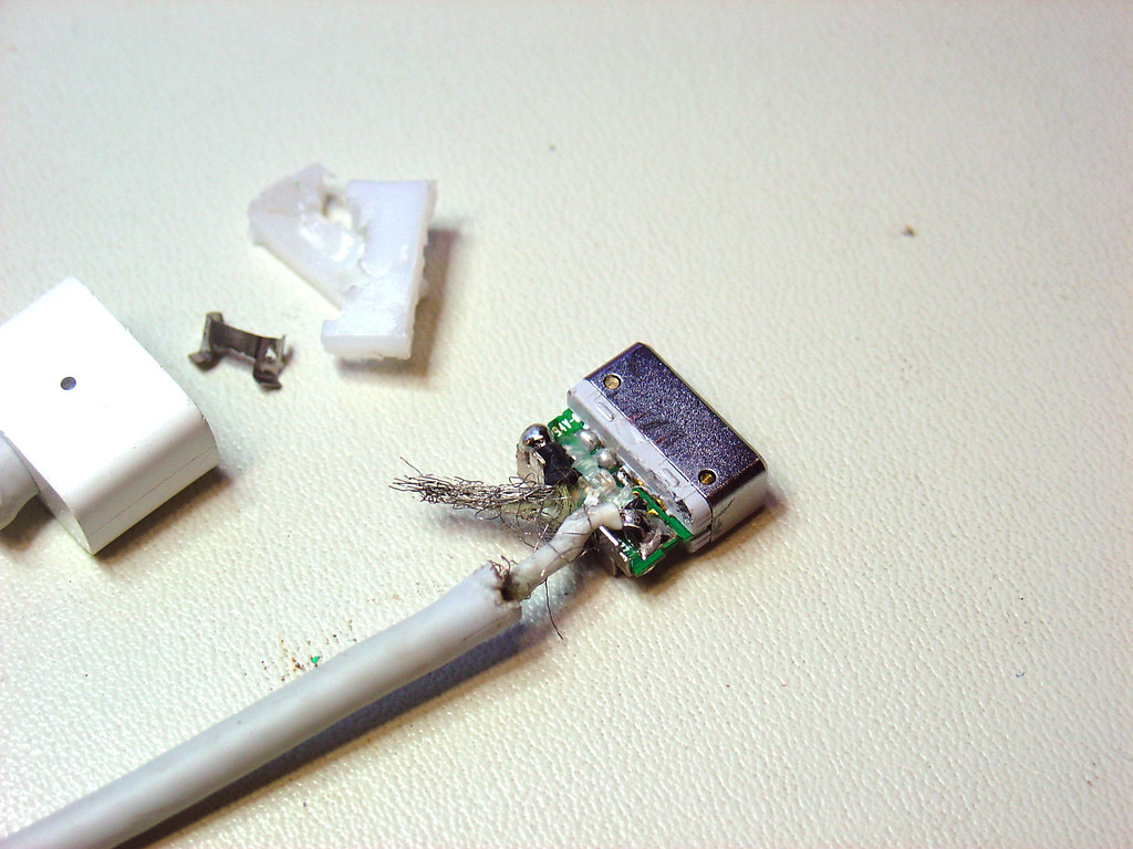
Why does a connector fail?
Sometimes, connector fails; there are many reasons behind this, and a few of them are listed here in this electrical connectors 101 guide.
- Wear and tear – frequent connection and dis-connection may lose them.
- Corrosion – water and moisture corrode the conductors, and the connector fails.
- Extreme temperature – sometimes, high and low temperatures cause failing the connector.
- Improper and wrong installation – this mystery sometimes happens by pushing and forcing the connectors at end terminals.
- Fretting causes failure of the connector
- Surface corrosion and increase in resistance retrain the flow of current.
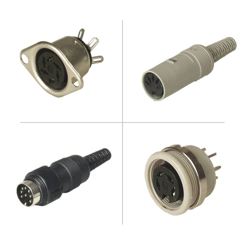
Other types of electronic connectors:
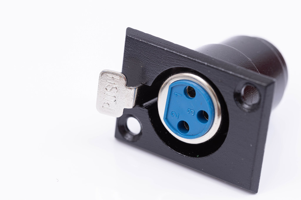
Circular electronics connectors
Circular electronics connectors are circular in cross-section. Circular connectors create a strong connection and contain circular contact and cylindrical housing. Due to strong, tight, and rigid connections, their mechanical performance is up to the mark. The very common use of circular electronics connectors is space, radio, military, aerospace, and communication devices.
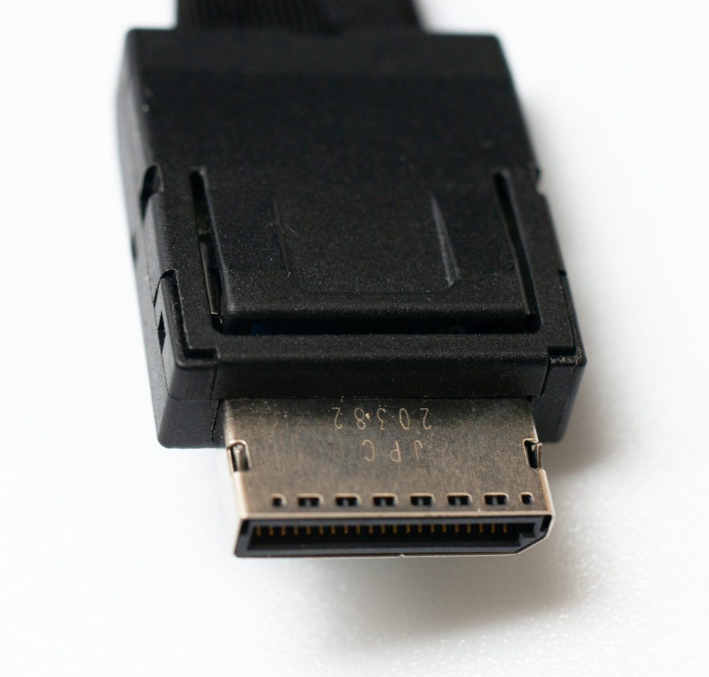
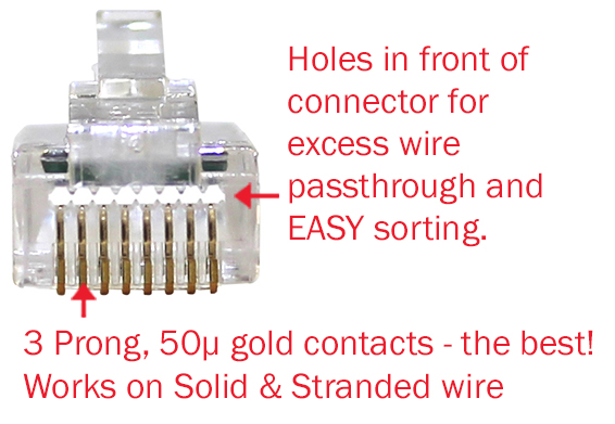
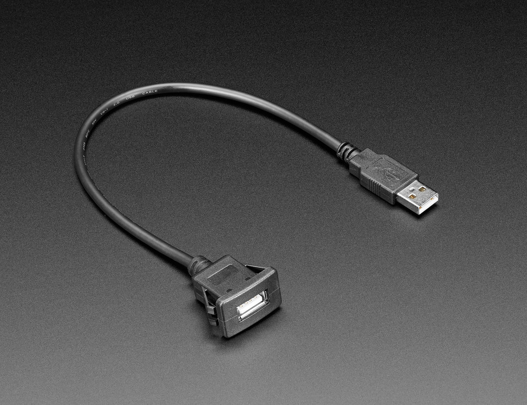
USB connectors
USB Connectors are very common and contain a USB end terminal at one side.

Hybrid connectors
Hybrid connectors are the same as the name assigned to them. Such connectors mix a couple of connectors either in series or random positions. House and inserts are two major parts of hybrid connectors.
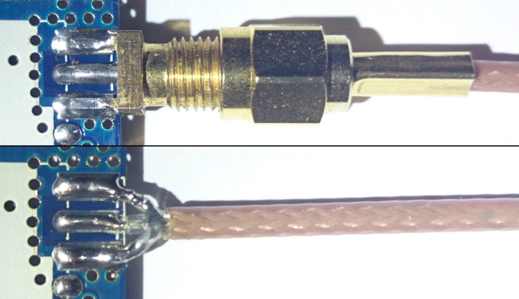
Soldered connectors
Soldered connectors are connected with the wires and cables with soldering.
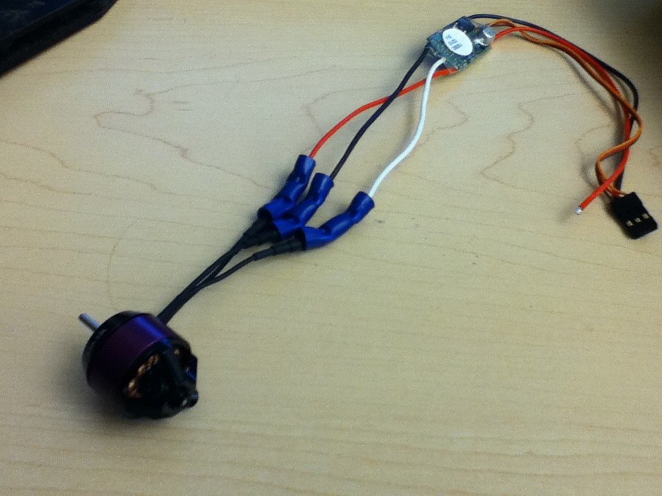
Blade connectors – are fit at end terminals using a terminal blade. This blade gets fits in hooks, screws, and other pins and connects the two devices. Here male and female connectors are attached by using any of the below-mentioned methods.
- Soldering of connectors
- Crimping of connectors
No electronics device on earth is without electronic connectors. Before opting for the right connector fit, engineers need to know the benefits, types, pros, and cons of every single type of connector. This article Electrical Connectors 101, explains the basic fundamentals, types of connectors, connectivity level, causes of failure, and physical properties of the electronics connectors.
Related posts:
 How to Maintain and Clean Light Fixtures
 Where to Install Motion-Sensing Lights?
 The Reason That Makes Homeowners Bound To Go For Commercial Lighting Upgrades
 HDMI Connectors: The Ultimate Guide To Connectivity
 Dual-Colour Printing Magic: Tips For Single Extruder 3D Printers
 Relay Module: A Guide for Functional Safety
 Different Types of Circuit Breakers and Their Use
 PCB Evaluation VS Development Board: Key Differences
 Take Initials To Buy Electric Outlets And Keep Safe From Any Harm
 ENERGTECH: A NEW WORLDWIDE DISTRIBUTOR OF UDOO NEO, DUAL, QUAD
 Top 10 Electronics Gadgets by Sony
 Online Store E-commerce: Significance, Types, Best Markets


