


Introduction
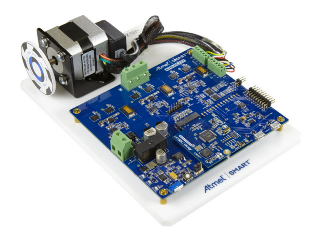
The MCP8024 BLDC Motor Driver Evaluation Board is used to show the drive capabilities of the MCP8024. The board incorporates the MCP8024 3-Phase BLDC motor gate driver and dsPIC33FJMC204 PIM to actualize a 6-step trapezoidal BLDC motor control. This board is used to evaluate the applications of the MCP8024 Microchip MCP8024 in the BLDC motor application. The board can drive a BLDC motor using a single onboard push button to start and stop the moto and one onboard potentiometer to set the motor speed. The MCP8024 is capable of driving a BLDC motor with a supply voltage of up to 28V and a current of 15A. It has a 6-step trapezoidal control algorithm coupled with5V and 12V LDO, high-to-low voltage translators, current sense op-amps, 750 mW buck converters,and Hall-effect inputs.
Features
- Input voltage range of between 7 and 28V
- 500mA gate drive current
- Drives BLDC motors of up to 15A
- 750 mW Buck regulator (with resistor-programmable output voltage)
- ON/OFF momentary contact switch
- PWM signal LED indicators
- Speed control potentiometer
- 5V and 12v Hall-effect terminal blocks
- An extra user-programmable momentary contact switch
- 100 pin dsPIC DSC PIM header
- SPI and C headers for user communication
- Programmable PWM blanking time for current switching spikes
- PICkit 3, MPLAB REAL ICE in-circuit emulator alongside an MPLAB ICD 3 debugger interfaces
- Programmable external MOSFET overcurrent protection
- Programmable PWM dead-time protection
- Complete “C” source code
Installation of the MCP08024
The kit
The MCP8024 TQFP BLDC Motor Driver Evaluation Board includes the following:
- MCP8024 TQFP BLDC Motor Driver Evaluation Board
- DsPIC33FJ32MC204 Plug-In-Module (MA330017)
- Information sheet
Installation
The board comes fully assembled and tested for driving a BLDC motor. It requires to be powered by an external voltage source that can supply 7V to 28V at the rated current. You also need a motor. There several user-configurable jumpers on the board. The information sheet should be of help in helping you configure them.
Running motor
- Turn the speed potentiometer fully counter-clockwise (to obtain the slowest speed setting) and then make a quarter turn in the clockwise direction to achieve 25 percent of the motor speed.
- Power the board.
- Press the RUN switch to start the motor
- To increase the motor speed, turn the potentiometer clockwise. To decrease the speed turn it counterclockwise
- Press and release the RUN switch to stop the motor
Configuring the MCP08024
The MCP8024 BLDC Motor Driver Evaluation Board has configuration registers that can be used to modify the operation of the device. To modify the parameters, the user can send commands to the MCP8024 via the DE2 communication bus. The DE2 communication bus is half-duplex. It’s also 9800 baud 8-data bits, 1-stop bit, 1-start bit, no parity communication link. One can add code to the evaluation board software firmware to communicate with the registers. The MCP08024 contains a subroutine that initializes the MCP8024 registers. One can write to three configuration registers. This is executed by sending SET_CFG_X command byte followed by the desired register value byte.
Read also:


