


The growing popularity
Has your phone vibrated today? Well then, you just experienced a brushless DC (BLDC) motor in action. BLDC motors are synchronous motors that are powered by direct current through a drive module or controller. BLDC motors have witnessed rapid growth in popularity owing to their construction that makes them superior to the brushed counterparts.
BLDC motors construction
- Rotor
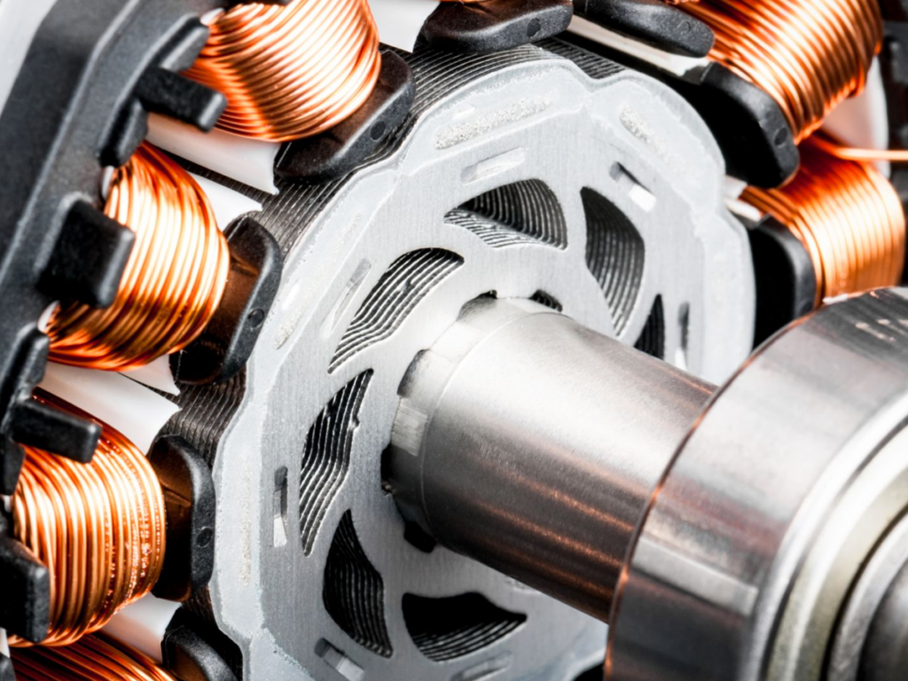
The rotor is made up of permanent magnets and its number of poles (North and South poles) varies from two to eight pairs. The permanent magnets are made from ferrite magnets. However, permanent magnets made from rare earth alloys are increasingly becoming popular owing to the advancement in technology. Rare earth alloys offer more magnetic density per volume while enabling the rotor to compress further for the same amount of torque. Such alloys also improve the size to weight ratio. There are two rotor designs for BLDC motors; the inner rotor and the outer rotor design.
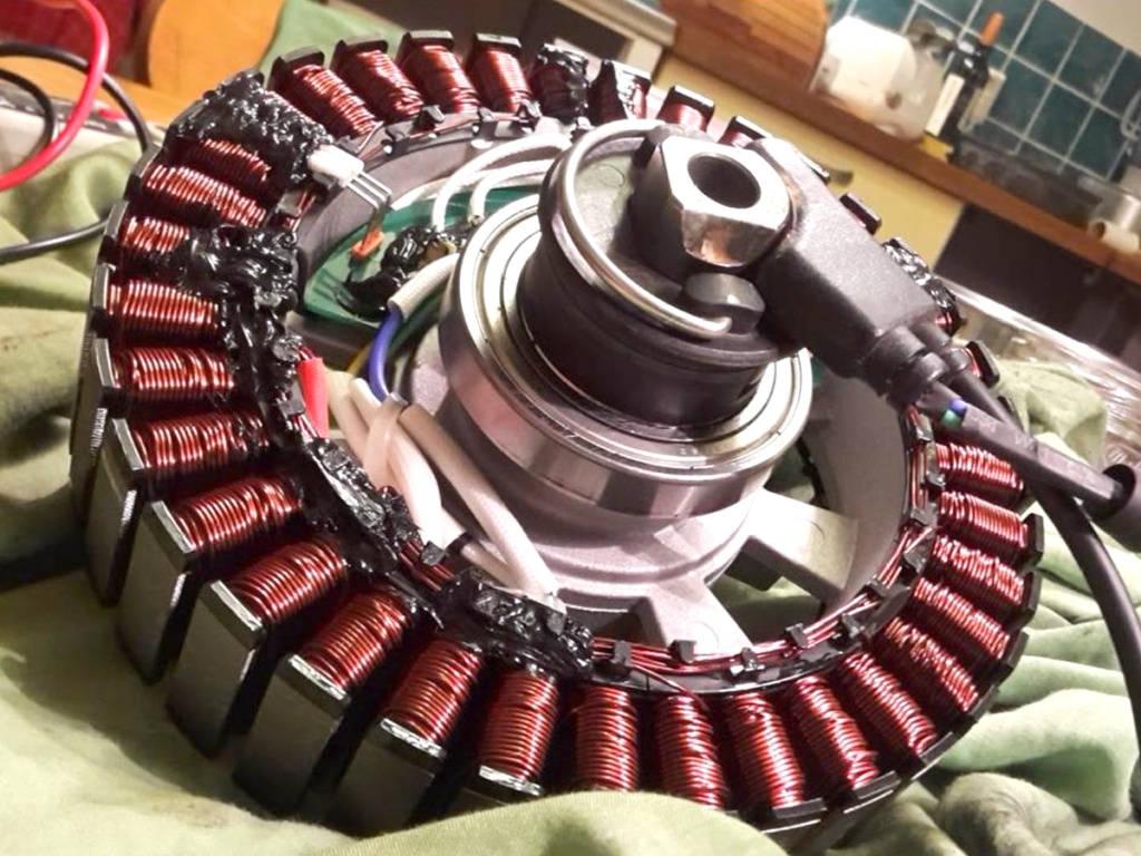
In the outer rotor design, the windings are located at the core of the BLDC motors while the rotor magnets surround it. The magnets act as the insulators hence reducing the rate of heat dissipation. BLDC motor with outer rotor design operate at lower duty cycle owing and a lower rated current owing to this design.
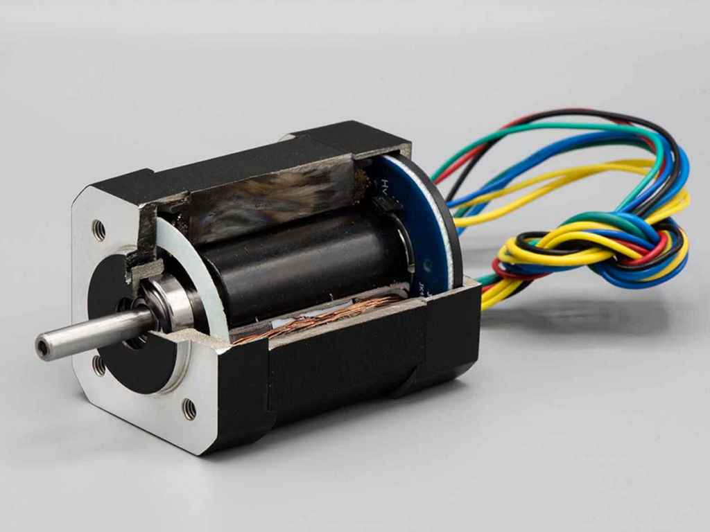
In the inner rotor design, the rotor is located in the center and is surrounded by the stator windings. This design enables the motor to dissipate heat, this directly impacts on its ability to produce torque. It is for this reason that most BLDC motors embody this design.
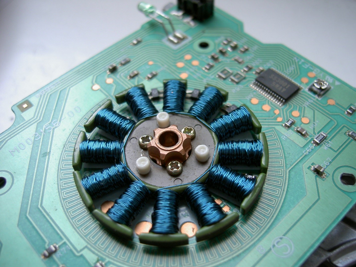
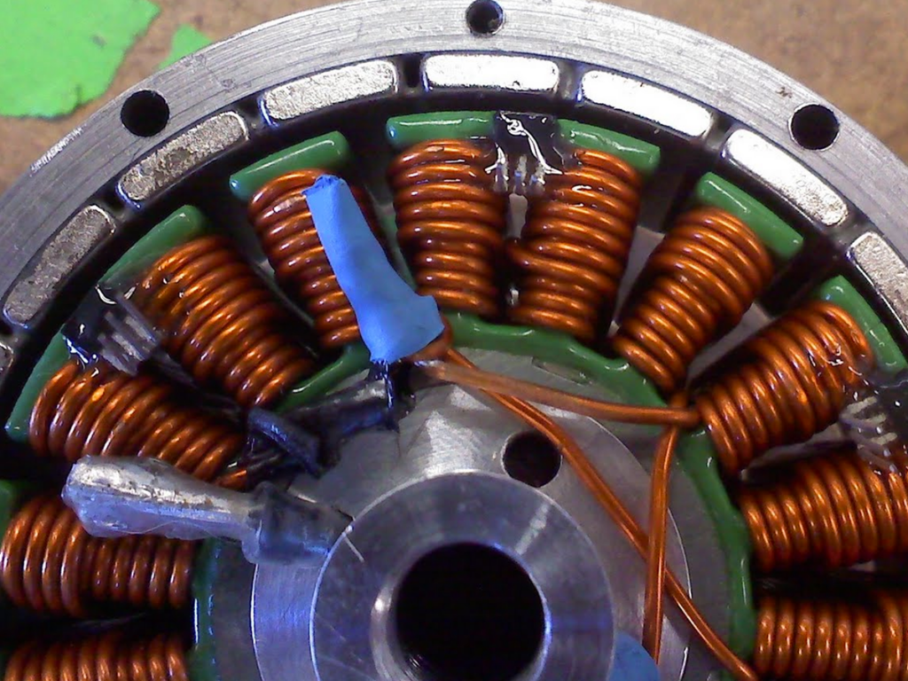
- Stator
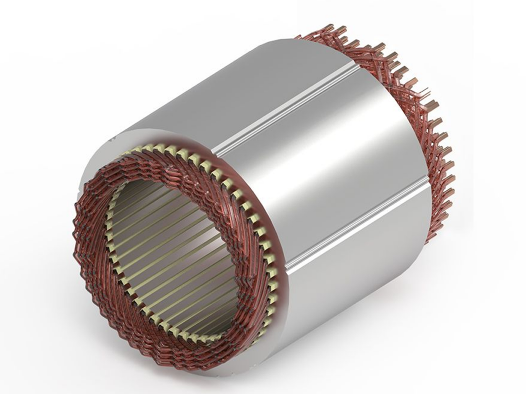
The stator is made up of stacked steel laminations that have windings placed in the slots that have been axially along the inner periphery. Many motors have three stator windings that have been connected in star. Every single winding has been constructed using numerous interconnected coils and is distributed over the periphery of the stator in a manner to form an even number of poles.
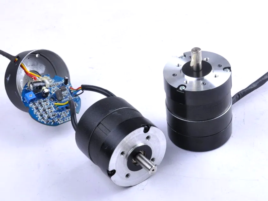
- Hall sensors
These sensors are used to sense the position of the rotor so as to establish which winding to energize. Most BLDC motors contain three Hall sensors embedded into the stator.
Theory of operation
The principle of operation of BLDC motors is the same as that of the brushed motors. The only difference is the implementation of the feedback. In brushed DC motors, it is implemented using brushes and commutators while in BLDC motors this feedback is implemented using Hall sensors and optical encoders.
Hall sensors operate on the principle that when a current carrying conductor is subjected to a magnetic field, an electromotive force is developed across the two sides of the conductor. When this field is reversed, the resulting voltage is reversed as well. When the magnetic poles pass close to the hall sensor, they generate either a HIGH or LOW-level signal. The combination of signals is used to come up with the sequence of commutation. This combination of signals is used to determine which windings to energize so as to keep the shaft rotating. The evaluation of the signals and the implementation of energization is determined by a controller or a driver module. Because commutation is done by a computer as opposed to mechanical brushes, BLDC motors are more precise. The motor’s torque is highest when the motor starts to move but as the field align, the torque reduces. To maintain the torque, the magnetic field generated by the stator is switched constantly.
Advantages of BLDC motors
BLDC motors have the following advantages over their brushed counterparts;
- Wear and tear are lesser since they do not have brushes
- There is no sparking
- Less electrical noise
- They are more precise.


