


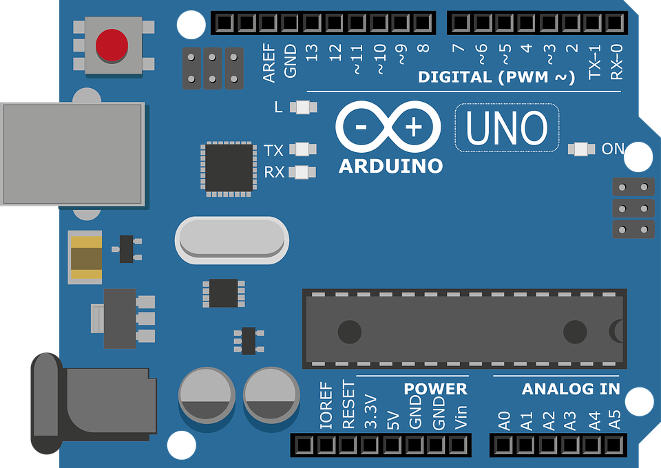
Arduino
Arduino boards embody multiple peripherals for communication with other devices. They include UART, I2C USB, and SP1. Wired communication has however proven to be difficult mostly so where the distance between the sender and receiver is considerable. As such, wireless communication comes in handy. Wireless communication is also critical in incorporating Arduino boards into the IoT environment. We have compiled several modules you can use to send data from an Arduino board to another Arduino or to the web.
Wireless data transmission
NRF24L01
The NRF244L01 transceiver module uses a 2.4GHz ban. It offers baud rates of between 250kbs and 2Mbps. In an open space and with lower baud rates, its range can stretch up to 100 meters. The NRF24LO1 can use 125 different channels which thus is able to have a network of 12 independent modems in one place. Each of the channels can have up to addresses or rather each of the units is able to communicate with 6 other units simultaneously.
The NRF24L01 consumes just 12mA during transmission. The power level is lower than that consumed by a single LED. The operating voltage ranges from 1.9 to 3.6V. The other pins tolerate5V logic thus making it easy to connect to an Arduino without the need for any logic converters.
Of the six pins, three are necessary for SPI communication and have to be connected to the SPI pins of the Arduino board. Notably, each Arduino board has different SPI pins hence the CSN and CE pins can be connected to any digital pins of the Arduino board. They are used for setting the module in standby or active mode. They are also used to switch between transmit or command mode. You do not use the last pin, it’s an interrupt pin.
You May Also Like This “How to Make a Simple Motion Sensor Led using Arduino“
ESP8266 Wi-Fi Module
The ESP8266 Wi-Fi Module can be used to communicate between two Arduino boards. It has a working voltage of 3.6V. It has an onboard 3.3V regulator that enables it to deliver safe, consistent voltage. It has 8 pins organized in two rows of 4 each. These pins are the RX, VCC, GPIO 0, RESET, CH_PD, GPIO 2, TX, and GND. The RX and the TX pins are used for communication. The CH_PD is used for powering down the chip while the RST is used for resetting the module. VCC and GND are used for powering the module. For this application, you do not need the GND and GPIO_2.
433MHz transmitter and receiver – 1597-1223-ND Kit
This kit contains the 433 MHz transmitter and the 1597-1223-ND receiver. They both operate at a frequency of 433Mhz. Its operational voltage is between 3 to 12 V. It has out of ½ Vcc. Its transmission range when working at 5V is 40M indoor and 100M in the open air.
HC-12 Module
The HC-12 module operates within the 433 MHz to 473 MHz frequency band. It embodies a total of 100 channels with a stepping of 400 KHz between each channel. It has a maximum transmitting power of 20dBM. It offers three working modes and has a built-in MCU. The operating voltage of the module is between 3.2V to 5.5V.
Summary
There are certainly numerous options to choose from when transmitting data wirelessly from an Arduino. They offer different capabilities hence you need to fully understand the demands of your application in order to pick the one that best suits your needs.
Related posts:
 Top 5 Industry Applications of Brushless Motors
 Constant Current LED Drivers
 An Introduction to Brushless Direct Current (BLDC) Motors
 Connectors for Energy Storage Systems and Applications
 An Introduction to the processes of Soldering and Welding
 LED’S FOR VERTICAL FARMING: THE ULTIMATE BUYING GUIDE
 Design Considerations for Cellular IoT in 5G Network
 RMS-to-DC Converters: Voltage & Power
 Aluminum Electrolytic Capacitors: Factors to Consider for Long Life
 Microchip Technology DM990101 IoT Ethernet Monitoring Kit
 Building a Data Management System for IoT Devices
 LED Connectors: Streamlining Assembly Efficiency


