


Current Sensing
In power-related applications, it is very important to know the amount of current flowing through the conductor. There are many ways of measuring current hence it is important to understand each one of them so that you make the right choice while considering cost, safety, form factor, power, and accessibility of the circuit.
Methods of current sensing
Contact current sensing
-
Shunt Resistor
Conditions that demand current sensing motor-control feedback, high-power charging from solar arrays, or power supply operation. In instances where current and associated voltages are low to moderate, the current measurement is simple, you just insert a current-resistor in the path of the current and then measure the voltage drop across the resistor. This method of inserting a resistor along the path of the current is regarded as the contact method of current sensing. In this method, it is important to address the issue of resistor sizing so as to avoid undesired voltage drop while providing sufficient voltage across the resistor so as to ensure accurate measurement. To achieve this, basic calculations need to be conducted and a suitable amplifier needs to be adopted.
If the current sensing resistor has been grounded on one end, this technique is regarded as low-side sensing. The low-side sensing circuit is straightforward. If the resistor is not grounded, that is regarded as high-side sensing. High-side sensing requires an amplifier to measure the voltage across the resistor. In many cases, the high-side sense circuit will need to be galvanically isolated to ensure safety or performance.
In applications where, high voltages and currents are common like in line-operated industrial and commercial motors and home metering, isolation of sensing circuitry is required for technical or regulatory reasons. It acts as a safety barrier by allowing the resistor to sense several thousands of volts above the ground.
The use of a current sensing resistor is only practical for single digit current levels. As current increases to double and triple digits, it becomes less feasible owing to the basics of Ohm’s law requiring that the resistor value should be kept low to maintain the voltage drop within an acceptable range. Unfortunately, small resistors demand special techniques for compensation and calibration making it complex and costly.
Non-Contact Current Sensing
Current transformer (CT)
This technique is based on the principle of a transformer. The transformer converts the high primary current into the smaller secondary current. This technique is common in high AC current measurement system. Since the CT is passive, driving circuits are not needed in its implementation. CTs can measure very high current while consuming very little power.
The downside of CTs is that very high primary current and substantial DC component in the current has the potential of saturating the ferrite material that is used in the core hence corrupting the signal. The other issue is that once the core is magnetized, it will contain hysteresis which will degrade the accuracy of the system unless the core is demagnetized.
Rogowski coil
The Rogowski coil measures the primary current resulting from an induced magnetic field whose magnitude is directly proportional to current causing the magnetic field. Basic electromagnetic theory dictates that a change in a magnetic field induces an EMF within a wire loop. The resulting EMF is proportional to the change in the magnetic field inside loop hence the output voltage is proportional to the time differentiation of the current.
Rogowski coil is unique in the sense that the coil has an air core hence has no hysteresis, non-linearity or saturation. This makes the coils are low cost, and improbable to DC offset hence can operate over a wide range of temperatures quite reliably.
The Rogowski coil relies on measuring a magnetic field hence is susceptible to interference from external magnetic fields hence due precaution to ensure that the coil does not come in contact with interference. Owing to the fact that the voltage induced in the coil is proportional to the rate of change, the Rogowski coil is connected to an analog integrator so as to provide an output signal which is proportional to the current flow.
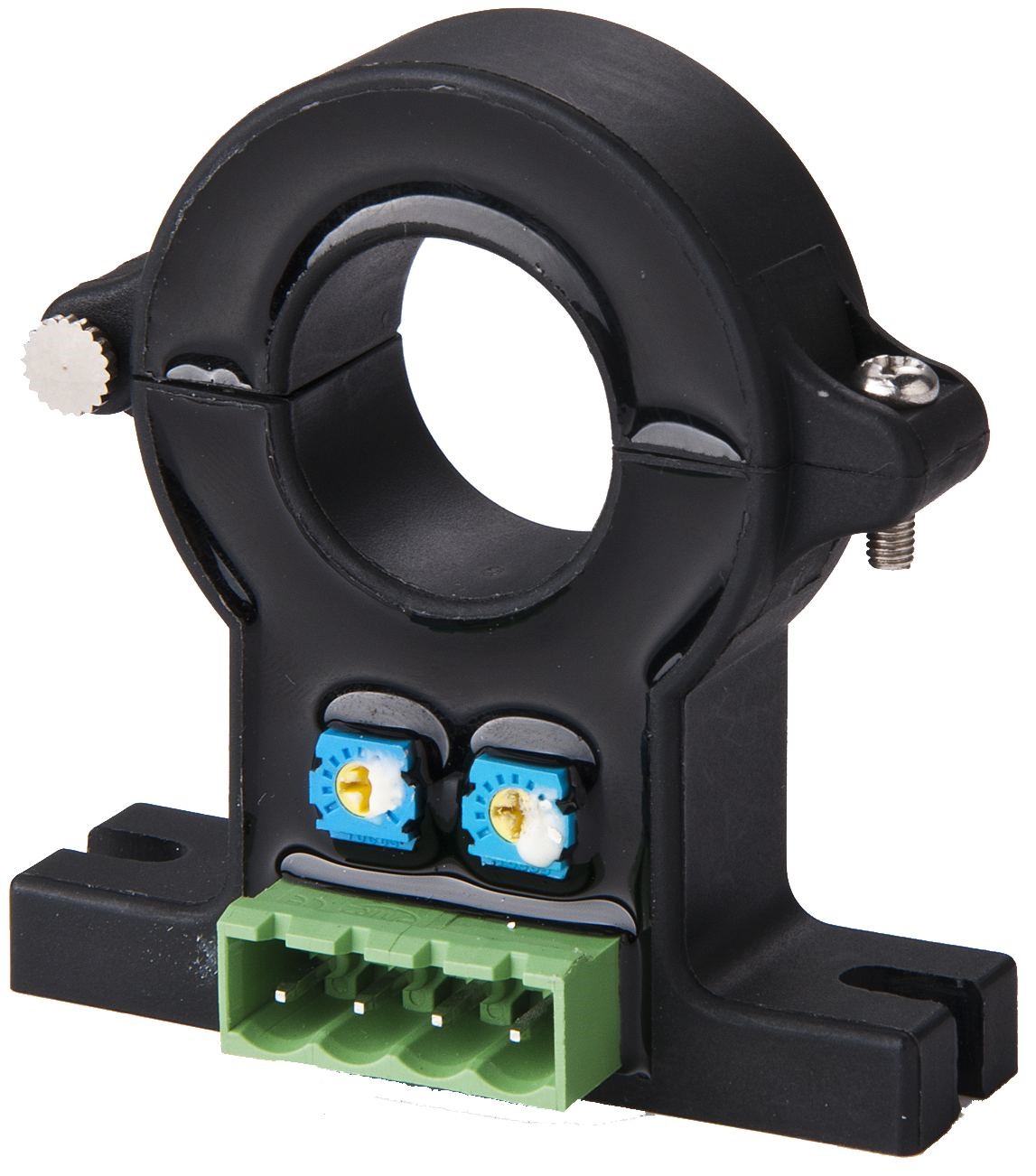
Hall effect sensors
Hall effect sensors are named after Edwin Hall, the man who discovered them in 1879. Hall discovered that when a conductor or semiconductor that has current flowing through it is placed perpendicular to a magnetic field, a potential can be measured at right angles to the current path.
Modern Hall-effect sensors incorporate a couple of elements, including amplifiers and active circuitry. The current to be measured is passed to the sensor array and the multiple Hall-effect devices within it produce accurate voltage measurements based the magnitude of the current. Hall sensors offer a dynamic range and perform well even at high current levels. However, they are subject to saturation, and temperature drift. The effects of saturation are minimized by choosing the proper components. Luckily, the drift is often negligible if a temperature compensated device is chosen.
Conclusion
Current measurement is not only more difficult but also intrusive compared to voltage measurement. It also requires that the current carrying conductor should be surrounded by or be routed through a sensing device. Rising current and voltage levels will require the implementation of galvanic isolation between the sensing circuit and the rest of the circuit. In current sensing, it is possible to provide isolation using electronic circuitry and components but the attractive alternative is to use a sensor that by itself isolated hence does not need additional isolation circuitry like current transformers, hall-effect sensors, and Rogowski coils.
Related posts:
 Programmable IoT Gateway Modems
 Why USB Type-C Circuit Protection is Vital
 How to Design Low-Power IoT Applications
 DESIGNING IOT SMART SENSORS WITH ULTRA-LOW POWER
 Multilayer Ceramic Chip Capacitors
 USB Type C: Why Circuit Protection is Critical
 Electric Motor: Understanding Types and their Uses
 DC Motors: Why do DC Motors have Brushes?
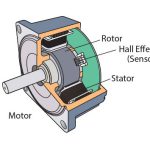 BRUSHLESS MOTORS- OPERATION, CONTROL AND APPLICATION
 Understanding constant current LED drivers
 Alps Electric World’s Smallest Detector Switches
 LED Lighting for Commercial Applications


2 Comments