


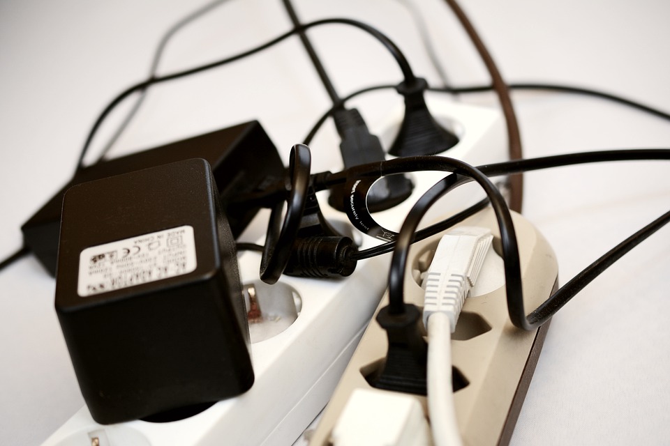
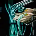
The zeal with which 5G is being received is evidence of the growing interest in millimeter-wave frequencies across the globe. Communication frequencies are growing every passing day hence the need for cables and connectors high frequency to move these high-frequency signals from one point to another.
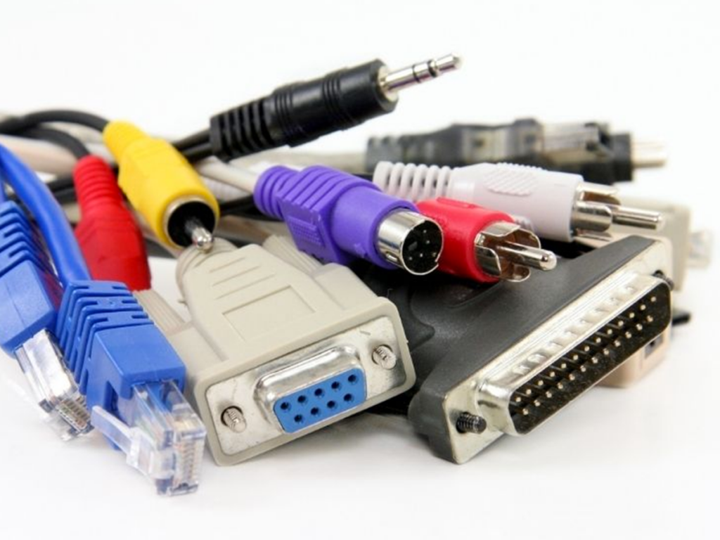
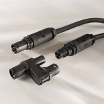
To meet this growing need for high-frequency transmission, terminating connectors that provide the standard RF architectures for the cables must meet the rigorous mechanical and electrical specifications. They are useful when linking coaxial modules within a system or when making a hookup between a device under test (DUT) and a test device.
The rapid development of services like paging and mobile phones has resulted in increased demand for coaxial cables. The rapid evolution and complexity of these systems have demanded progressively rigorous electrical and mechanical specifications depending on the suitable placement of materials, design and development and process technologies.
Factors to consider when choosing cables and connectors for high frequency
In choosing these cables and connectors head for high frequency, the following factors are put to account;
- Impedance
- Shielding
- Attenuation
- SWR
- Crush strength
- Intermodulation
- Power ratings
Impedance
The resistance of the coaxial cable is defined by the lengths and the outside performers and by the density of the dielectric filler, which also defines the cable speed. The default 50ohm RF impedance is a balance between optimal attenuation and optimal lower impedance power management.
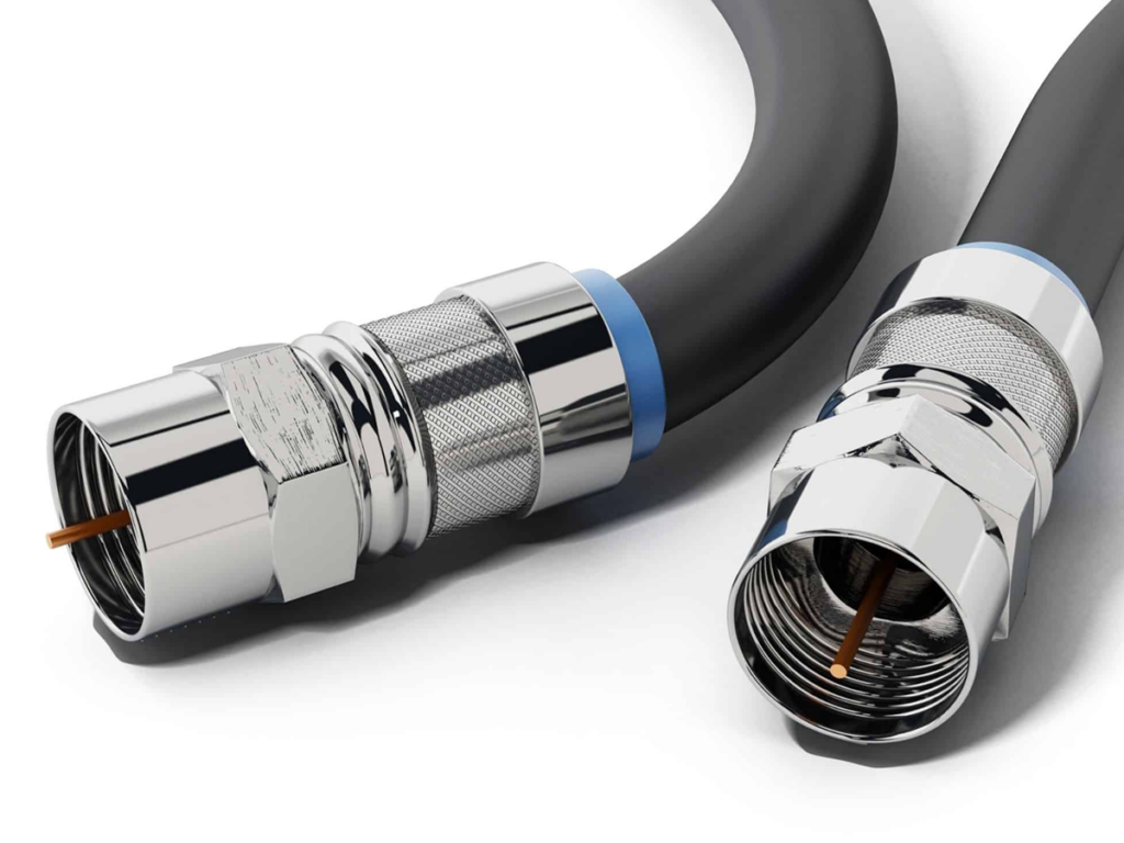
Shielding
Effective RF shielding with a consistent outer conductor is a feature of the RF cord. The design is almost completely non-radiating and makes the use of several feeders in close quarters, without any binding or cross-discussion between cables. High shielding depends on the ratio of the density of the outer conduit to the volume of skin at the operational frequency.
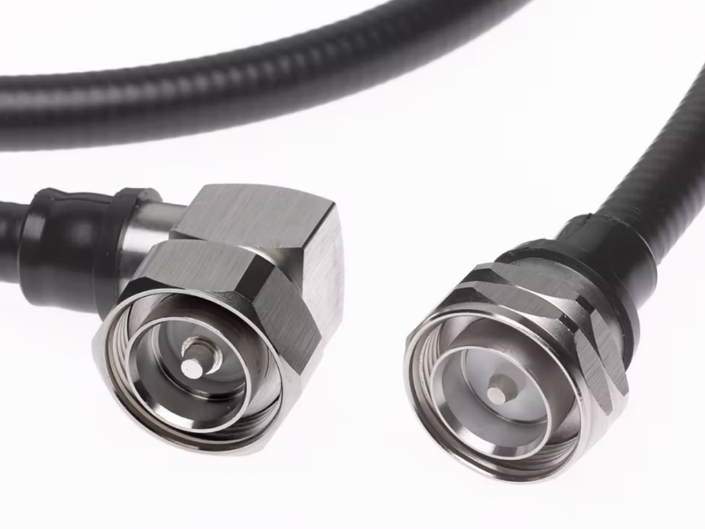
Attenuation
RF signals must be conveyed between the antenna and the communications equipment with minimum failure for maximum scheme productivity. The system loss budgets usually require a feeder loss of 1 or 1.5 dB. Attenuation varies with the diameter of the cable roughly inverse proportion. For a specified cable size, optimal conductor corrugation layout and choice of the best conductor and dielectric materials can achieve the optimal balance of electrical and mechanical qualities.
SWR
Three-source reflection influence the determined SWR of a cable and its ending connectors: a reflection from the connector nearest to the measuring equipment; reflection from the connector at the far end of the cable, diminished by cable attenuation; and subsequent reflections generated within the cable itself
Crush strength, power ratings, and intermodulation are not to be overlooked as the adequately impact cable output. RF feeder cables and connectors are finely machined to optimize wireless throughput, use advanced materials and are fabricated using meticulous process technologies to achieve the electrical and mechanical properties necessary.
Below is a table showing individual cable type and frequencies
| Connector type | Frequency range (GHz) |
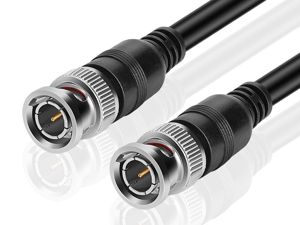
| BNC | DC to 4 |
| TNC | DC to 4 |
| 7-16 DIN | DC to 7.5 |
| Type N | DC to 11 |
| C | DC to 12 |
| SMA | DC to 18 |
| Precision SMA | DC to 26.5 |
| 3.5 mm | DC to 26.5 |
| 2.4 mm | DC to 50 |
| 2.92 mm/K | DC to 40 |
| 1.85 mm | DC to 65 |
| 1.00 mm | DC to 110 |
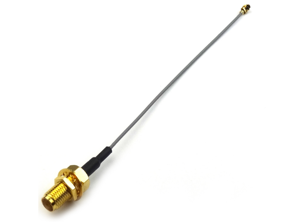
High-frequency connectors are accuracy connectors used for testing and measuring, or for implementations with sensitive low loss, phase stable, high-frequency microwave up to 67 GHz. These are made of high-quality components to enable a longer life span and improved endurance.
It should be noted that:
- Two grades of coaxial cable are thicknet and thinnet
- Coaxial cables were initially used for LANs
- UTP and STP are two types of twisted pair media
- UTP is the most commonly used cable on LANs today
- Fiber is subject to less noise interference but is more expensive
- Light signals are sent down fiber cables
- WLANs use spread-spectrum technology to reduce noise interference
- WEP is an encryption security method designed to protect wireless transmissions
- Other security methods such as VPN, EAP, and LEAP are used to supplement WEP and provide even more secure transmissions
- RJ45 connectors are used with UTP cables
- Fiber-optic cables offer high-bandwidth connections over long distances
- Access points and wireless network cards are two devices used on wireless networks
- Wireless signals can deteriorate with distance
- Fiber is subject to less noise interference but is more expensive
- Light signals are sent down fiber cables
- Light signals obey the law of refraction and reflection
- Multimode and single-mode are two types of fiber-optic cables
- SC and ST connectors are used with fiber-optic cables
- Wireless networks are useful for locations where it is difficult to install cables
Wireless systems span a very wide range of applications from consumer to automotive, across many business verticals. Such cable connections can be small junction cables for routing to very long runs in transmitters and vertical elevators in tall buildings
Related posts:
 Audio Amplifier: Introduction to TAS2505-Q1EVM Audio Amplifier
 LED Lighting Fixture: How to Repair Your Fixture
 The Power Of Efficient RF Connectivity In The 5G World
 The fast-approaching revolution of industrial IoT
 LED LIGHTS: THE ULTIMATE BUYER’S GUIDE 2017
 Understanding UK Wiring Colours: A Comprehensive Guide
 Top 10 Electronics Gadgets by Sony
 Nector M Power System from TE Connectivity
 New Temperature Sensor with ICs Simplify Design for Circuits
 How to Choose an Arduino Shield
 Raspberry Pi Camera Case Protects your Camera
 Key Capabilities of Bluetooth LE to Make the Future of Audio


